Benchmark explainer · 14 min read
BenchCAD, explained simply
A test that asks AI models to build real mechanical parts, not by drawing pictures, but by writing the code that a CAD program runs. Here are the parts, how the AI builds them, and what the scores actually mean.
What BenchCAD is
BenchCAD is a benchmark for programmatic CAD. Instead of asking an AI to generate a mesh or an image, it asks the AI to write a short Python program in CadQuery. That program is then run through a real CAD kernel (OpenCascade, the same engine behind FreeCAD), which turns it into a solid 3D part. The part is compared against the correct one, and the score comes from geometry, not from a language model's opinion.
Think of it like a cooking exam where the student hands in a recipe rather than a photo of a dish. The examiners cook the recipe exactly as written and taste the result. If a step is missing, the dish is wrong, no matter how good the recipe sounded.
Every part was designed by domain experts from an industrial standard, with parameters sampled from real specification tables (for example DIN 338 twist-drill diameters or ISO 4014 bolt sizes). Programs that failed to compile, took longer than 30 seconds, or produced a broken solid were thrown out, and every surviving render got a human sign-off. The data is CC-BY-4.0 on Hugging Face; the evaluation code is MIT on GitHub; the paper is arXiv:2605.10865.
The parts the AI has to build
These are not abstract shapes. They are the bread-and-butter components of mechanical engineering: fasteners, gears, springs, brackets, flanges, pipe fittings, panels, enclosures, and a few playful ones like a phone stand and a Gridfinity bin. Each family comes in easy, medium and hard variants, built on different starting planes (XY, XZ or YZ), so the AI cannot memorise one orientation.
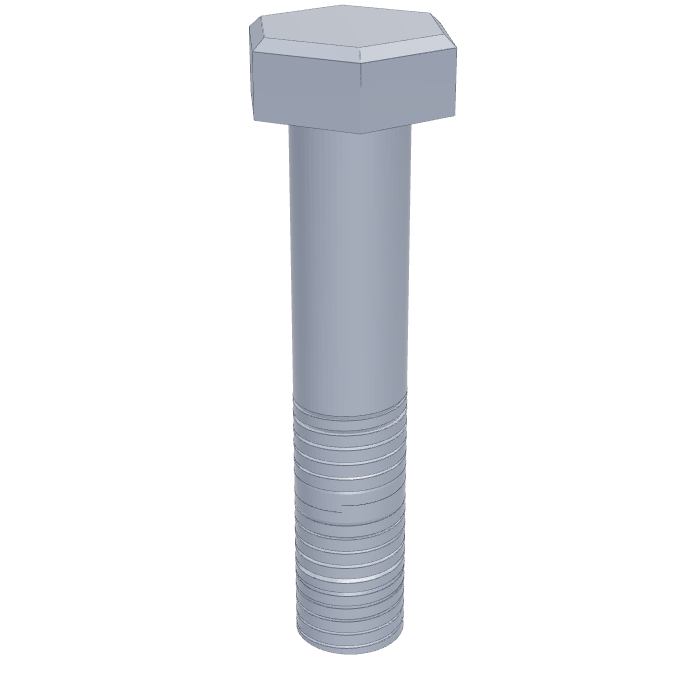
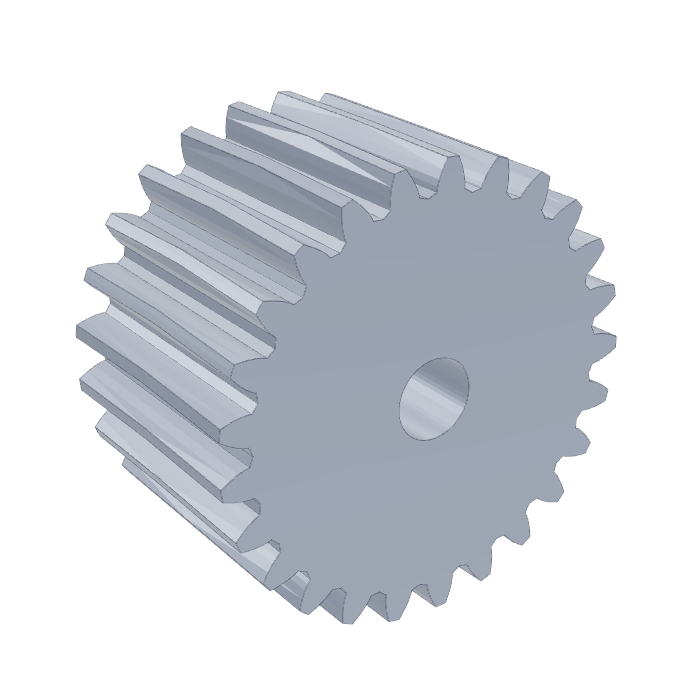
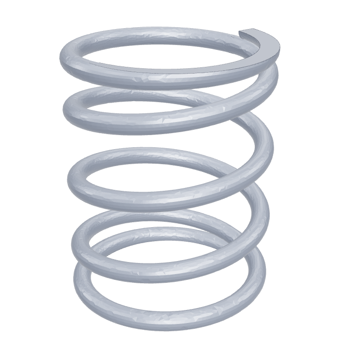
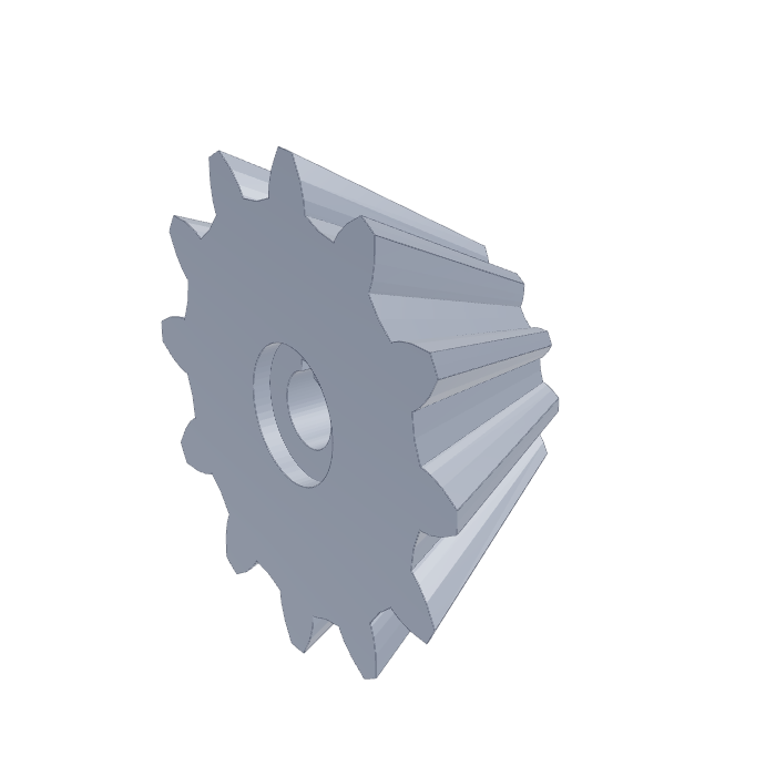
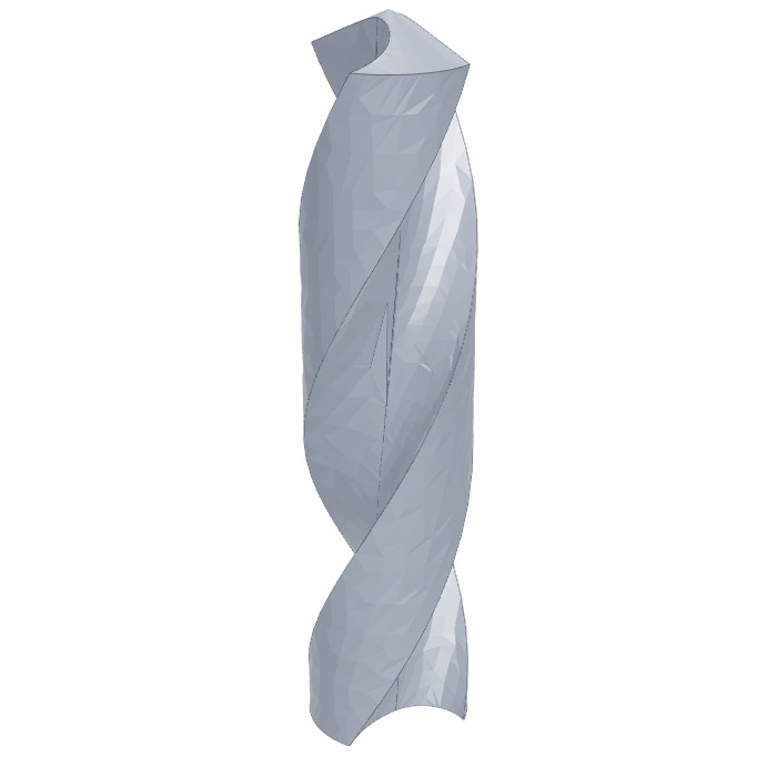
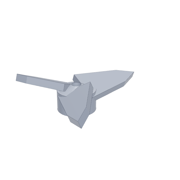
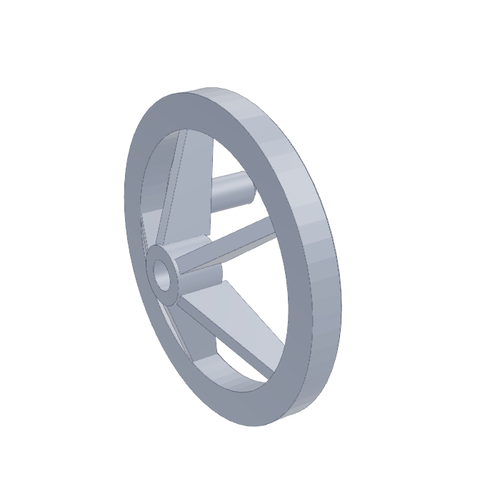
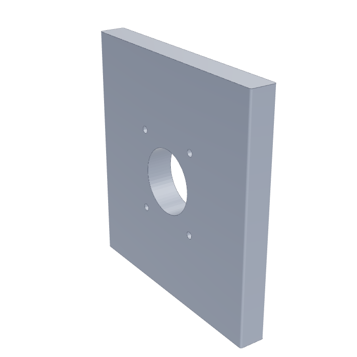
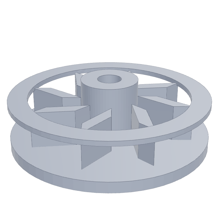
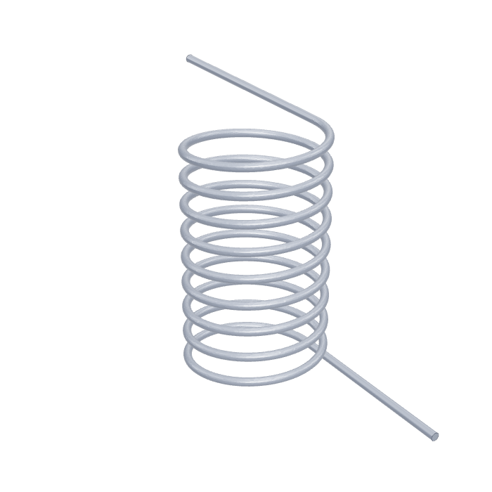
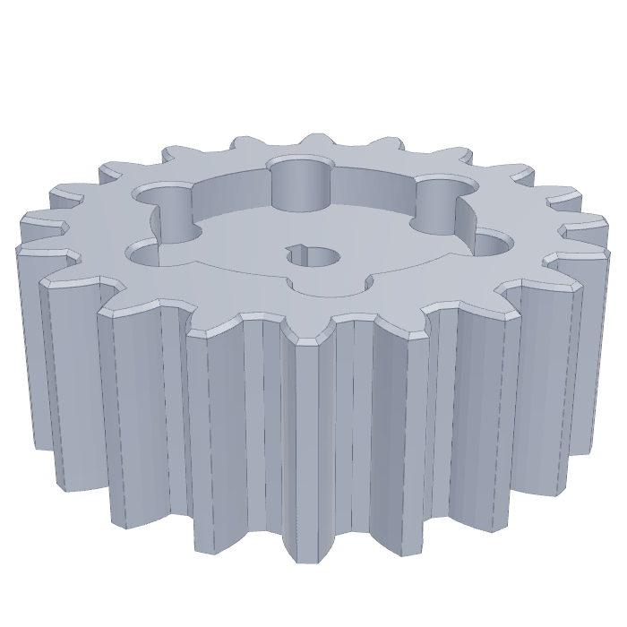
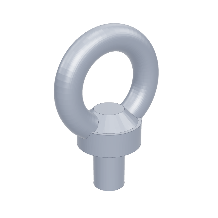
Twelve of the 106 families. The standard shown is the one the family's parameters are sampled from; "custom" families have no formal standard.
All 106 families
What the AI sees, and what it creates
In the main task the AI never gets the 3D model. It gets four small pictures: front, right, top and an isometric view, each 134 by 134 pixels. From those it has to write the CadQuery program. Here is a real example from the dataset, a medium-difficulty ISO 4014 hex bolt.
Input: four views
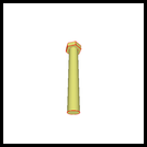
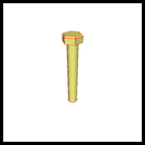
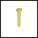
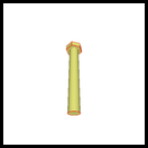
Output: a program, not a picture
import cadquery as cq

result = (
    cq.Workplane("XY")
    .circle(8.0)
    .extrude(110.0)
    .faces(">Z").workplane()
    .polygon(6, 27.71)
    .extrude(10.0)
    .edges(">Z")
    .chamfer(1.5)
)
The ground-truth program for the bolt above, exactly as stored in the dataset.
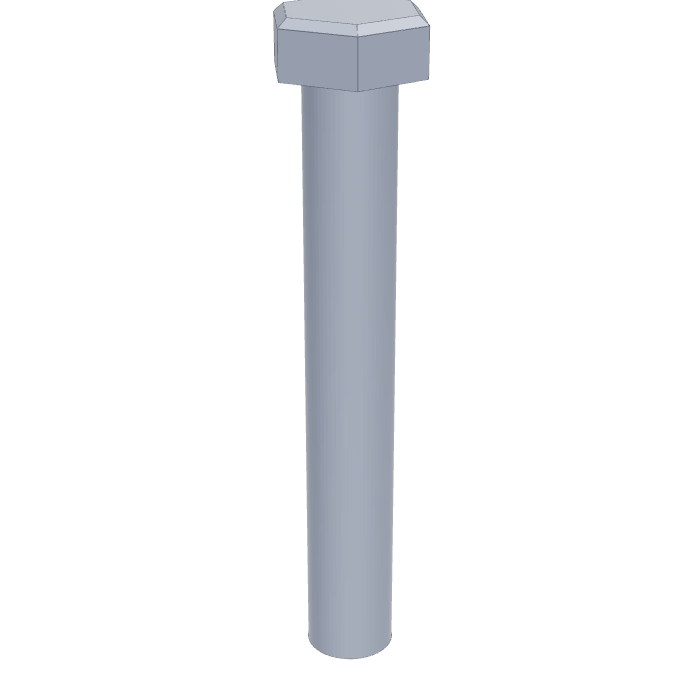
How the code becomes a part
CadQuery reads like a recipe. Each line is one modelling step, and each step works on the result of the previous one. This is exactly how a human engineer works in Fusion 360 or SolidWorks, just written out as text.
- Pick a sheet of paper.
Workplane("XY")chooses the flat plane you will sketch on. Get this wrong and the whole part comes out lying on its side, which is one of the most common AI mistakes. - Draw the outline.
circle(8.0)draws a circle of radius 8 mm. For the head,polygon(6, 27.71)draws a hexagon 27.71 mm across its corners. - Pull it into a solid.
extrude(110.0)stretches the circle 110 mm upward, like pushing clay through a cookie cutter. That is the shank. - Move to the new top face.
faces(">Z").workplane()says "find the face pointing up, and start sketching on it." Then the hexagon is extruded 10 mm to form the head. - Finish the edges.
edges(">Z").chamfer(1.5)bevels the top edges of the head by 1.5 mm. Fillets, holes, cuts and mirrors work the same way: select something, then apply an operation.
Bolts are easy. Harder families need operations that stack-and-extrude cannot fake: revolve spins a profile around an axis (a knob, a pulley), sweep drags a profile along a path (a spring is a circle swept along a helix), loft blends between two different cross-sections (a bevel gear), and twistExtrude twists the outline as it rises (a twist drill). BenchCAD keeps a per-family list of these essential operations, and one of the paper's main findings is that models routinely replace them with simpler sketch-and-extrude patterns that look roughly right from the outside and are wrong everywhere else.
The three tests
1. Vision2Code: pictures in, program out
The core task, and the one the leaderboard headline comes from. The model receives the four views and must return a complete, runnable CadQuery program. If the code crashes, the score for that part is zero.
2. Question answering: does the model understand the part?
The same 2,400 numeric questions are asked twice: once with the pictures (Vision QA) and once with the source code (Code QA). Asking the same question both ways separates "can it see" from "can it reason". Questions are grouped into four levels:
| Level | What it tests | Example question |
|---|---|---|
| L1 | Recognise the part and its basic features | How many chamfer operations are applied? |
| L2 | Understand CAD operations and their order | Along which axis does the primary extrusion occur? |
| L3 | Read engineering parameters like a designer would | What is the size of the largest chamfer in this part? |
| L4 | Reason about what happens if the design changes | If all .union() operations were removed, how many separate solid bodies would remain? |
3. Code Edit: change one thing, break nothing
The model is handed a working program and a one-sentence instruction, and must return a minimally changed program that produces the target part. There are 748 of these across five edit types, from trivial to nasty:
| Type | Name | Example instruction |
|---|---|---|
| T1 | Literal replacement | "Increase the I-beam total height from 120 to 160." |
| T2 | Chained transform | "Rotate the entire part 90° about Z, then a further 45° about X." |
| T3 | Relative computation | "Set each knuckle radius equal to half the leaf width; the leaf, pin holes and bore stay the same." |
| T4 | Feature edit | "Drill a 6 mm diameter through-hole along the Z axis." |
| T5 | Geometry rebuild | "Replace the square inner passage with a hexagonal one of the same across-corners size, keeping everything else unchanged." |
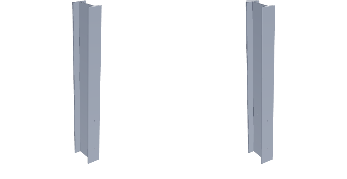
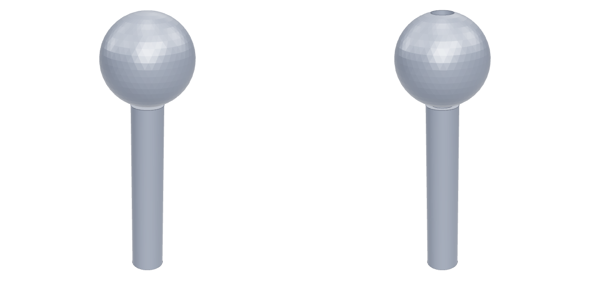
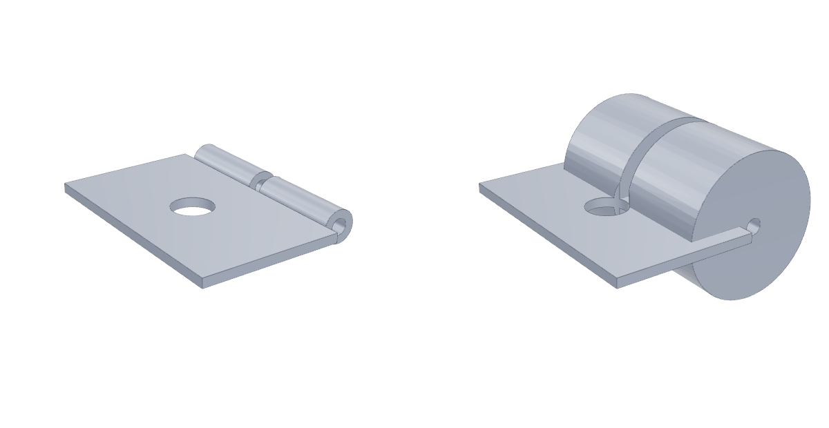
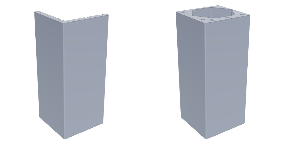
Before and after solids, rendered from the STEP files shipped with the benchmark. Both sides use the same camera so the change is the only thing that moves.
How the scores are computed
Everything is graded by executing code and comparing geometry. There is no AI judge anywhere in the loop, so a score is reproducible by anyone who runs the same programs.
Voxel IoU: the main number
Take the AI's solid and the correct solid. Centre each one, scale it so its longest side is exactly 1, and fill it into a 64 × 64 × 64 grid of tiny cubes (voxels), a bit like building both parts out of 262,144 LEGO bricks. Then count:
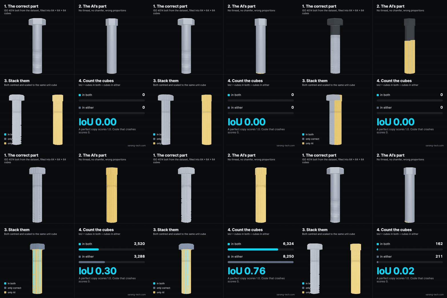
A perfect copy scores 1.0. Code that crashes scores 0. A score of 0.27, roughly where the best general-purpose models sit today, means that when you stack the two parts on top of each other, only about a quarter of the combined volume is shared. The outer body might be there, but threads, chamfers, holes and the exact proportions are off, and so is often the orientation.
The leaderboard's IoU-score is the average of this number over all parts, with non-executing parts counted as 0. The exec% column tells you how often the code ran at all.
The composite "total"
Raw IoU rewards blobs. A rough cylinder in the right place already scores decently against a bolt. So BenchCAD also reports a fused score that pays for the details:
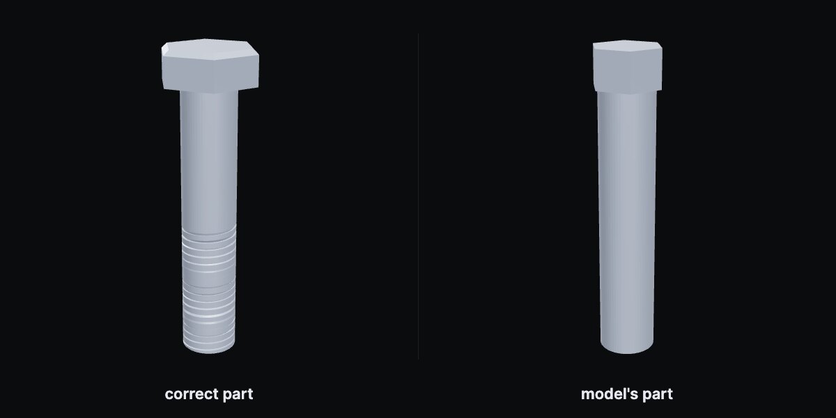
Both parts centred, scaled to a unit cube and filled into the same 64³ grid. Shared cubes divided by cubes in either. The brick score from above.
Measured on this pair: 6,356 shared cubes of 8,292 → 0.77. Code that crashes → 0.
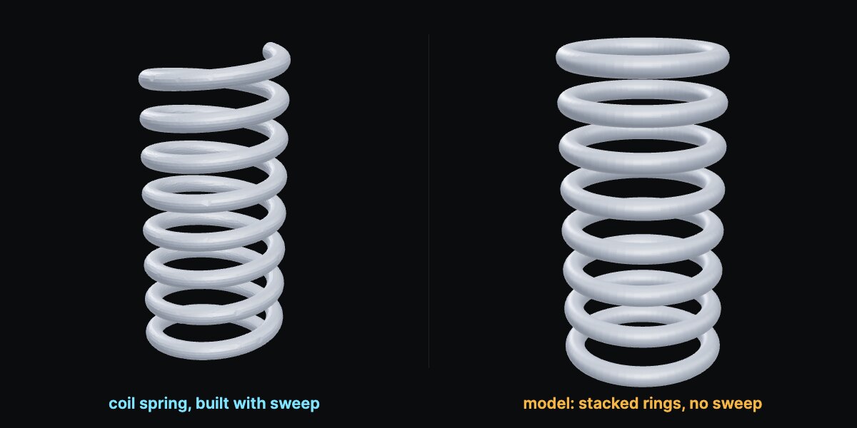
Each family lists the operations it genuinely requires. A coil spring must use a sweep. A bevel gear must use a loft. A twist drill must use a twisted extrude. Pass or fail per part, read straight from the code.
Measured on this pair: the left program calls sweep, the right never does → 0 on this term regardless of shape. Their overlap is only 0.09 anyway; thin coils are unforgiving, so this term mostly bites when the overlap is decent but the method is wrong.
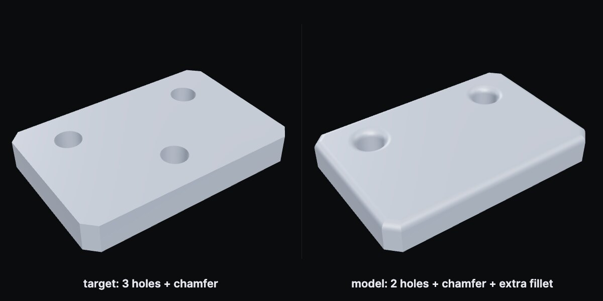
Count the holes, fillets and chamfers in each program. Precision: of the features the model added, how many are real. Recall: of the real features, how many did it add. F1 is their harmonic mean.
Measured on this pair: target has 3 holes and 1 chamfer. Model has 2 holes, the chamfer, and an extra fillet. Precision 3/4, recall 3/4 → 0.75.
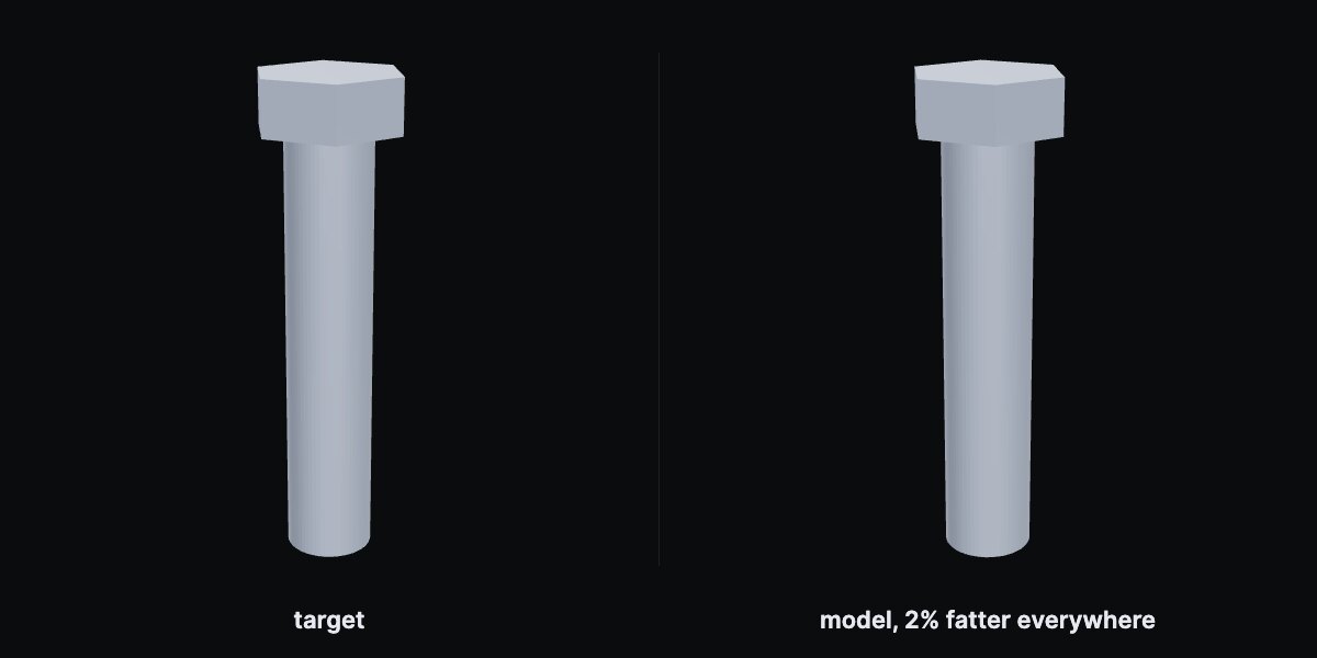
Sample points on both surfaces. For each point, find the nearest point on the other surface. Average all those distances, then map to a 0 to 1 score. Punishes being slightly off everywhere.
Measured on this pair, as a fraction of the part's size: average gap 0.28%, worst gap 0.79%. Small and uniform, exactly what this term is built to catch and what IoU shrugs at.
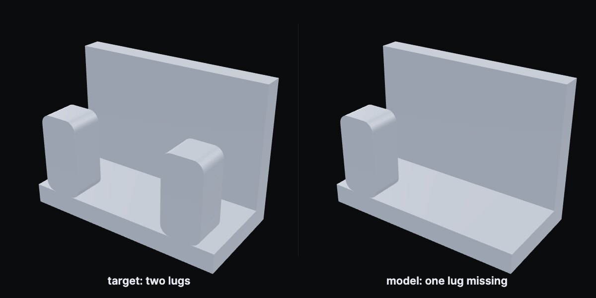
Same sampling, but take the largest gap anywhere instead of the average. One badly wrong region dominates, however good the rest is.
Measured on this pair: average gap only 1.4%, but worst gap 40% of the part's size, the distance from where the missing lug should be to the nearest surface. The average forgives it. The worst case does not.
All five pairs are real CadQuery parts built for this article; every number above was computed on them with the benchmark's definitions, on the same 64³ grid, not typed in. The paper does not publish the exact mapping from surface distance to a 0 to 1 score or its feature-matching rules, so those two rows show the raw measurements.
Code Edit: how much of the gap did you close?
For an edit, measuring IoU against the target is unfair, because the untouched original already overlaps the target a lot (a 6 mm hole barely changes a knob). So the score asks a better question: of the distance between the original and the target, how much did your edit cover?
Example: the original knob already overlaps the target at 0.88. If the edited program reaches 0.97, the score is (0.97 − 0.88) ÷ (1 − 0.88) = 0.75. Returning the program unchanged scores exactly 0, which is why the "no-change baseline" on the leaderboard is 0.000. Making the part worse also scores 0.
Question answering: exact, or proportionally close
Answers are numbers, and the grader is type-aware. Counts, yes/no answers and line numbers must match exactly: an off-by-one is simply wrong. Dimensions and ratios are scored by how close you got, in proportion:
So answering 9.5 when the truth is 10 earns 0.95, and answering 20 earns 0.5. If the sign is wrong the score is 0. The paper summarises this as "±5% tolerance for ratios and exact match for integers"; the released grader implements the proportional version above. The final QA number is the mean over all questions, reported per level and in total.
Where models stand
Numbers from the public BenchCAD leaderboard as of September 2026. All rows except the ones marked self-reported are re-graded by the benchmark authors from raw model outputs. Where a model appears more than once on the board (different prompts or runs), the best row is shown.
Vision2Code, IoU-score (higher is better)
The bar runs to 1.0. Nobody is close. The paper also reports that a small 2B model fine-tuned with reinforcement learning on BenchCAD data reaches 0.75 on parts from the same families, which says the ceiling is far higher than what general models currently show.
Code Edit accuracy (with thinking enabled)
Question answering, total (same 2,400 questions)
| Model | Vision QA | Code QA | Gap |
|---|---|---|---|
| Gemini 3.1 Pro | 0.587 | 0.838 | 0.251 |
| Claude Opus 4.7 | 0.530 | 0.829 | 0.299 |
| GPT-5.3 | 0.514 | 0.823 | 0.309 |
| GPT-4o | 0.464 | 0.726 | 0.262 |
| Blank-input baseline | 0.375 | 0.223 | – |
The gap column is the whole story in one number. Given the code, models answer well. Given only pictures of the same part, they lose 25 to 30 points. Reading a part off a drawing is the bottleneck, not the reasoning that follows.
The catch
The headline numbers flatter the models a little, and the failure analysis in the paper is the honest part:
- Coarse right, fine wrong. Models recover the outer body of a bolt but drop the thread and the chamfer. On IoU that costs little; on a real drawing it is a different part.
- Wrong sheet of paper. Extruding from XY when the target was XZ is common, and it wrecks the overlap score even when everything else is right.
- Faking the hard operations. A twisted bracket comes back as two flat brackets at right angles, with the twist simply missing. Before fine-tuning, an open-weight baseline in the paper used revolve, sweep and loft in 0% of cases where they were essential.
- Standards blindness. A DIN 2095 spring should have closed and ground ends with a varying pitch. Models produce a uniform helix.
- Collateral damage in edits. The paper reports that roughly 64% of edits that hit their target also silently changed something unrelated. A high edit score does not yet mean a safe edit.
Put together: today's best general models can write CAD code that runs 80 to 95% of the time, can edit existing designs reasonably well, and still cannot look at four views of a hex nut and hand you back the right hex nut. That is the gap BenchCAD is built to measure, and it is measured with a CAD kernel rather than a rubric, which is why the numbers are worth trusting.